
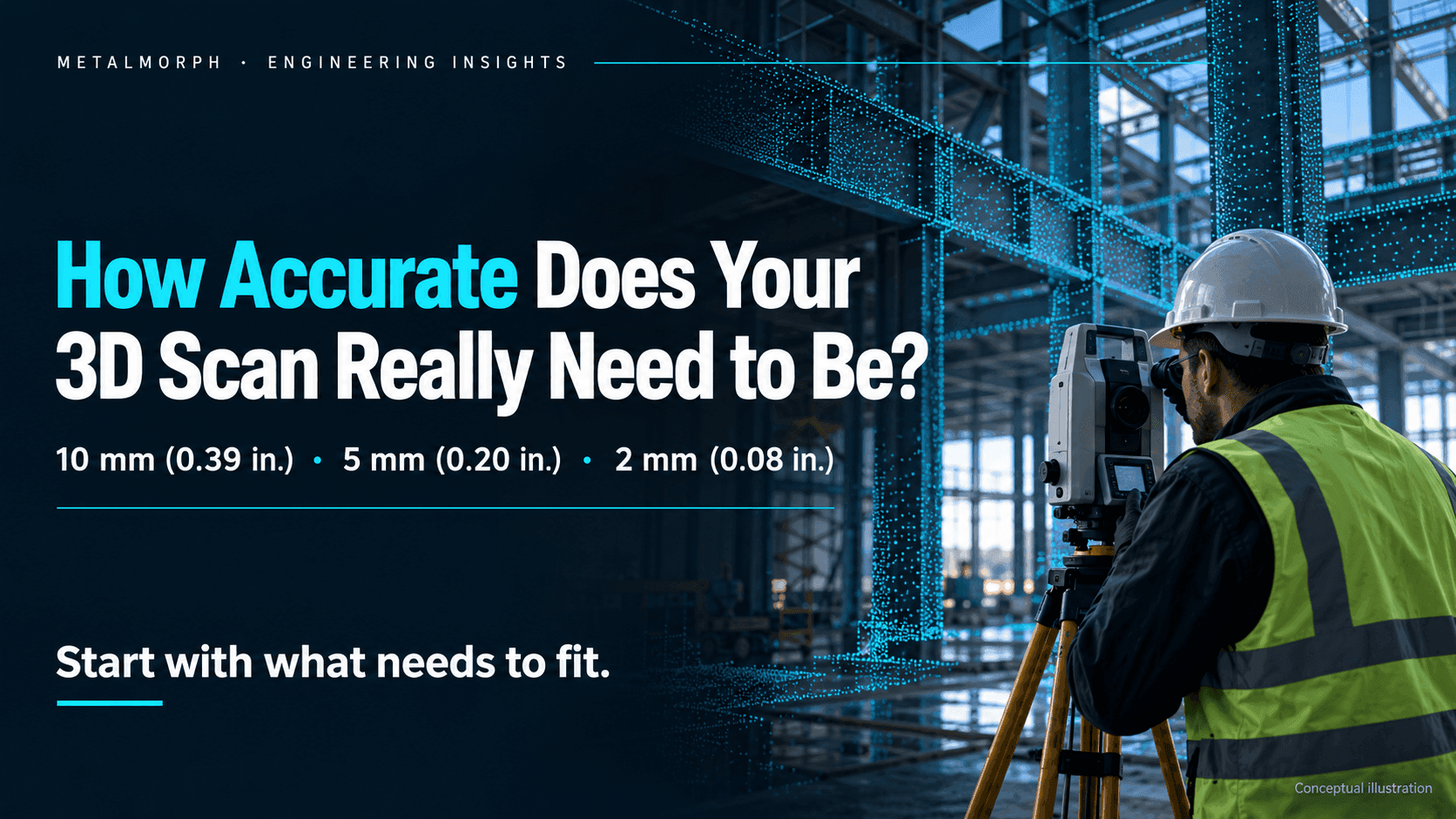
10 mm, 5 mm, or 2 mm? It depends on what you’re building.
The right accuracy starts with how much variation your project can accommodate.
A wall that sits 5 mm (about 0.20 in.) from its expected position may not cause a problem.
A bolted connection with the same offset could prevent assembly.
Same difference. Very different consequences.
What matters is how much adjustment is available when it’s time to install.
The same principle applies to 3D scanning. Capturing a space for layout planning and measuring connection points for prefabricated components are different tasks. They require different measurement approaches.
In our previous article, we explored why scanner specifications don’t necessarily translate into accuracy across an entire site.
The next question is more practical: How accurate does your project’s data need to be—and what does it take to achieve that?
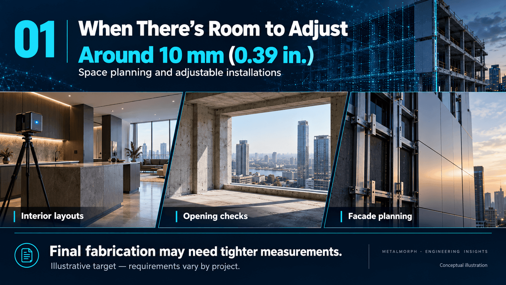
Around 10 mm (0.39 in.): When There’s Room to Adjust
Imagine planning furniture or architectural finishes inside an existing building.
Knowing the wall locations, ceiling heights, opening sizes, and clearances helps the team evaluate layouts and identify conflicts. If components can be repositioned or gaps accommodated with trim, data accurate to around 10 mm may be useful.
Examples include checking space around window openings, planning aluminum composite material (ACM) panel layouts, and evaluating furniture placement.
For a limited area that does not need to tie into the project’s survey coordinates, a terrestrial laser scanner may provide what’s needed, provided the scan alignment and key dimensions are checked.
But consider a cabinet that must fit tightly between two existing walls.
Suddenly, the available adjustment is much smaller. The same is true of windows or panels with tight installation clearances. Their final fabrication dimensions may require more precise verification.
That’s why the installation detail matters more than the product category.
Where can the installer make adjustments, and where does the fit need to be exact?
Answering that question helps distinguish data suitable for layout planning from measurements suitable for fabrication.
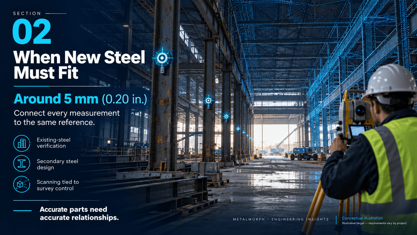
Around 5 mm (0.20 in.): When New Components Must Fit Existing Steel
Now imagine designing secondary steel to support a new facade on an existing structure.
The drawings show evenly spaced columns and consistent beam elevations. The installed structure may be slightly different.
Before new members are fabricated, those differences need to be understood. For this type of existing-steel verification or reverse engineering, a measurement target around 5 mm may be appropriate.
At this level, the relationship between components matters as much as the shape of each component.
One column might be captured accurately. But if the scan containing the opposite column is slightly misaligned, the calculated distance between them could still be wrong.
This is where 3D scanning tied to survey control becomes important.
Think of survey control as a shared coordinate framework. Every area is measured against the same reference, so geometry captured in different locations can be positioned and checked consistently.
The scanner captures surfaces. The control network provides the reference for locating those surfaces within the project.
This becomes particularly important across large buildings. Individual scans can look good while the relationship between distant areas remains uncertain.
Before scanning begins, the measurement plan needs to establish where control points will be placed and how the position of each area will be verified.
Around 2 mm (0.08 in.): When a Few Millimeters Can Affect Assembly
A prefabricated module arrives on site.
The crane lifts it into position. The crew brings the connections together.
But the bolts won’t pass through.
The mismatch may be tiny compared with the size of the module, yet the connection may have very little room to accommodate it. With multiple connections, adjusting one end can move another out of alignment.
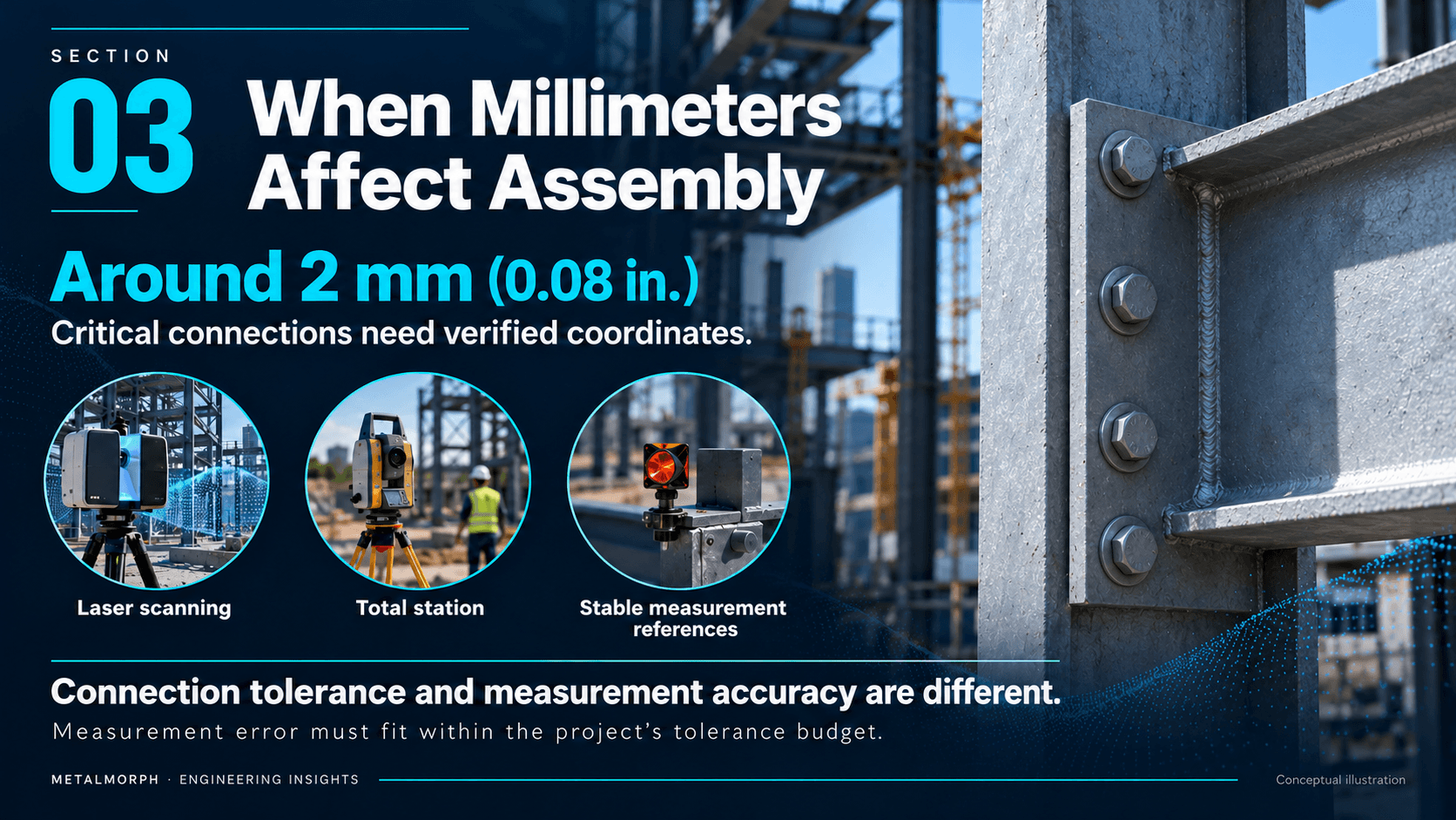
Bolt-hole locations and spacing, support-pier positions and elevations, and working points used to position complex structures can require measurements around 2 mm—or tighter, depending on the connection requirements.
There is an important distinction here: connection tolerance and measurement accuracy are not interchangeable.
If a connection allows only 2 mm of positional variation, the allowable measurement error may need to be smaller. Fabrication and installation also need a share of that tolerance.
For this type of work, laser scanning and precise coordinate measurement are planned together.
The scanner captures the surrounding geometry. A total station measures or checks critical locations. High-precision prisms, stable mounts, and purpose-made measurement templates may also be needed.
Just as important is defining exactly what will be measured.
If a plate edge is rough or a connection is hidden behind a pipe, zooming in on the point cloud may not reveal a reliable reference. A clearly defined, repeatable measurement point may need to be established, with a known relationship to the actual connection.
As tolerances tighten, identifying and verifying the right points becomes more important than simply collecting more points.
Higher Accuracy Requires a Different Measurement Plan
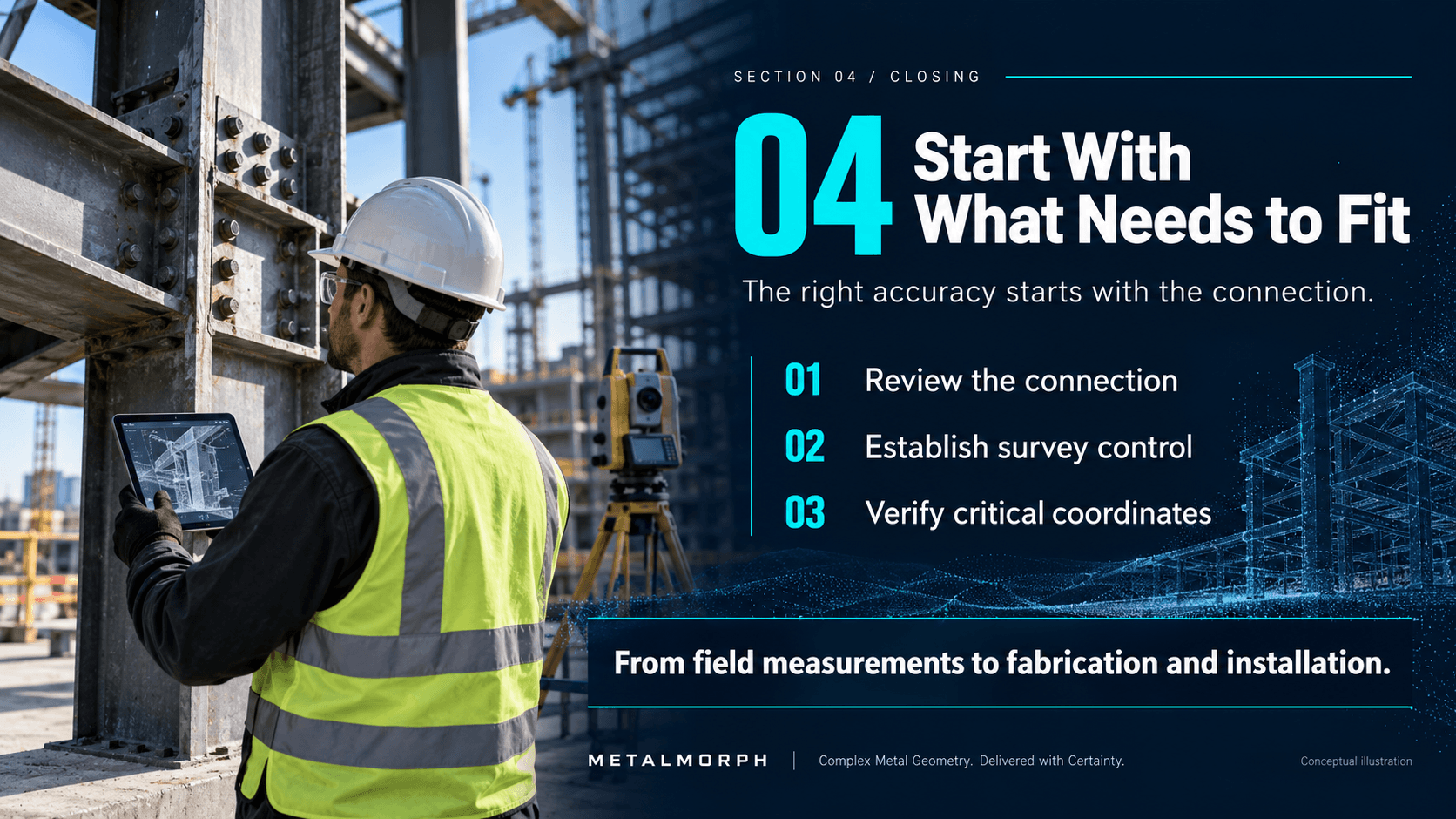
10 mm, 5 mm, and 2 mm are not settings you simply select on a scanner.
As requirements become more demanding, greater attention must go into survey control, critical-point measurement, and independent verification.
That does not mean every surface needs the highest possible accuracy. An adjustable finish panel and a tightly constrained bolted connection have different needs.
At MetalMorph, those differences shape the measurement plan.
We start with what will be fabricated, where it connects, and how much adjustment is available during installation. From there, we define the scanning scope, survey control, and checks needed at critical interfaces.
The accuracy levels discussed here are illustrative, not universal standards or equipment guarantees. Inch equivalents are rounded for reference. Actual requirements should be established around the project’s fabrication and installation tolerances, the dimensions being checked, and site conditions.
Before commissioning a scan, start with one question:
“How far could this location be off before it causes a problem on site?”
Turning that answer into reliable dimensions and coordinates is what connects field measurement to successful fabrication and installation.
Complex Metal Geometry. Delivered with Certainty.
MetalMorph | Engineering · Digital Fabrication · Dimensional Verification

