
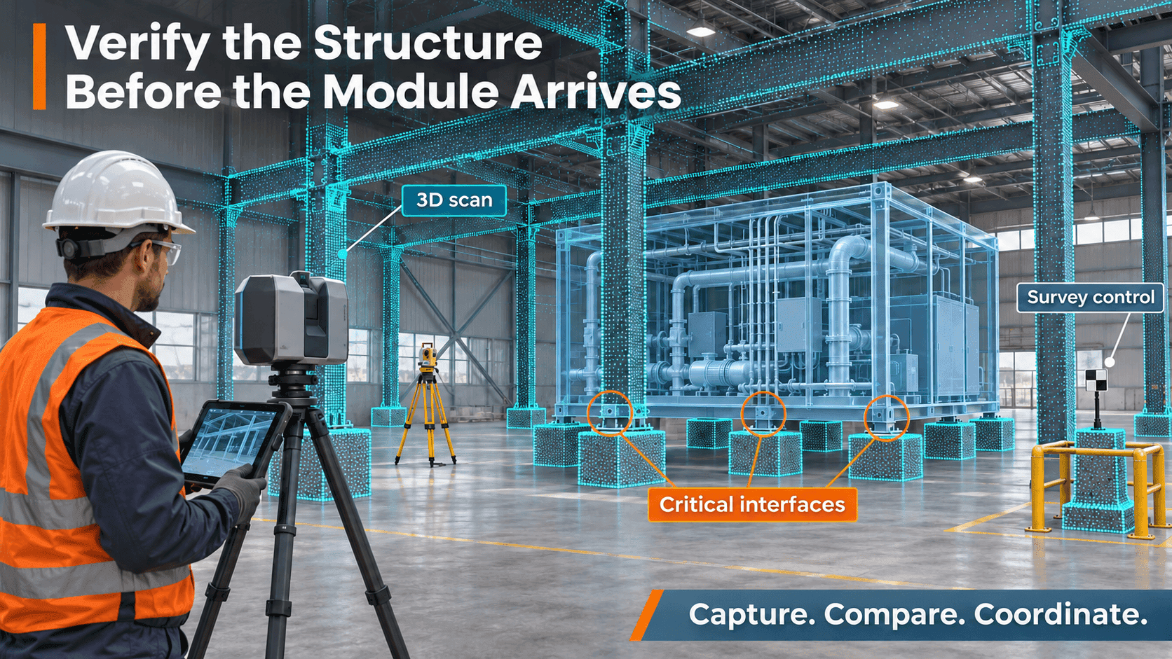
Why the structure you measure matters as much as the module you manufacture.
A prefabricated equipment module arrives on site.
Its dimensions have been checked. The fabrication team has followed the approved model. The connections are ready.
But when the module is lowered into position, one support sits too low. Another connection is slightly out of alignment.
The module may be exactly as designed. The structure receiving it may have changed.
For modular construction, reliable fabrication starts with knowing what is actually there—and when it was measured.
In our previous article, we looked at how installation tolerances shape the measurement plan. This time, the question is about the structure itself.
What “Allowable” Really Means
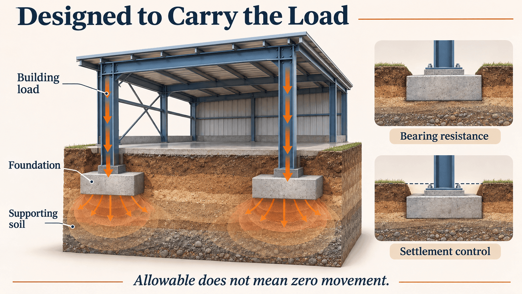
Foundation design considers the building loads and the ground supporting them. In an allowable-pressure approach, the bearing pressure imposed by the foundation must remain within the applicable allowable value, with loads and pressures compared on a consistent basis.
Two checks matter: sufficient resistance against ground failure, and acceptable total and differential settlement. A bearing-capacity value alone does not replace a settlement assessment. [1]
The word “allowable” can sound like a promise that nothing will move. It is not.
It describes an engineering limit under defined conditions. The relevant question is how much movement the structure—and everything connected to it—can accommodate.
A Strong Surface Does Not Tell the Whole Story
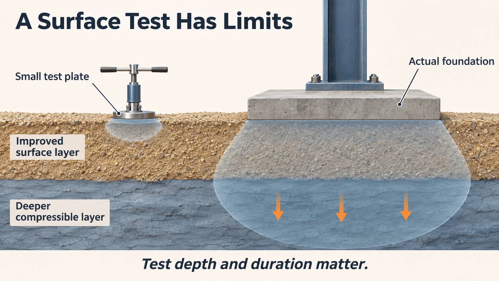
Where near-surface ground is unsuitable, engineers may specify replacement, improvement, or another foundation solution.
That work must address the ground affected by the actual foundation, including deeper layers where relevant.
A small plate load test and a full-size building foundation do not load the same volume of ground. A short test also cannot, by itself, establish the long-term consolidation response of deeper clay. Test scale, duration, and the soil profile all matter. [2]
In saturated compressible clay, loading can cause excess pore-water pressure to dissipate over time as the soil compresses. Further compression may continue after primary consolidation. [3]
A borehole log showing lower SPT N-values at depth is a reason to investigate, rather than proof of a specific future settlement. Soil type, compressibility, stress history, groundwater, layer thickness, and the additional stress from the building all affect the assessment.
The practical lesson is simple: a satisfactory result near the surface does not automatically describe everything happening below it.
Uneven Movement Changes the Installation Geometry
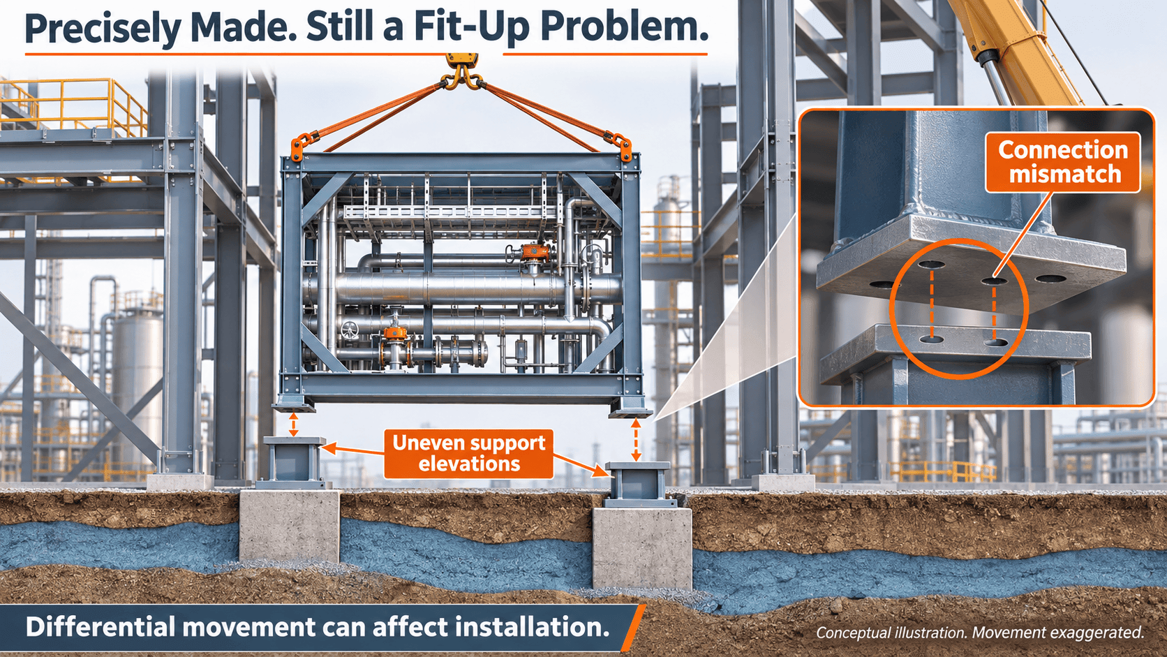
Ground conditions can vary across one building footprint. So can foundation loads and support stiffness.
When supports settle by different amounts, the result is differential settlement. It can change relative support elevations and rotate or distort the supported structure. [1]
That matters because a module connects to several locations at once.
An installer might adjust one support successfully, only to find that a connection at the opposite end no longer lines up. A rigid module cannot independently follow every change in the structure around it.
Buildings are designed around movement and serviceability requirements. Sensitive finishes, equipment, and connections may impose tighter limits than the primary structure alone.
For modular work, those interface requirements need to be part of the coordination from the beginning.
Fabrication Accuracy Is Only One Part of Fit
Consider a prefabricated pipe rack or equipment skid.
Its frame may satisfy the fabrication specification, while its receiving supports differ from the coordinates used to manufacture it. Support levels, anchor positions, opening dimensions, and adjacent services all influence whether installation succeeds.
Settlement is one possible contributor. Erection variation, structural deflection, concrete shrinkage, temperature, and construction sequencing may also affect the measured geometry.
A mismatch should therefore prompt verification of the interfaces and investigation of the cause. A scan alone cannot establish that settlement caused a deviation.
For facilities such as semiconductor plants and nuclear facilities, where equipment interfaces can be especially demanding, the measurement scope should follow the actual installation requirements.
The useful question is not simply, “Was the module made accurately?”
It is, “Was it made for the conditions it will meet?”
Scan the Structure Before Releasing the Interface
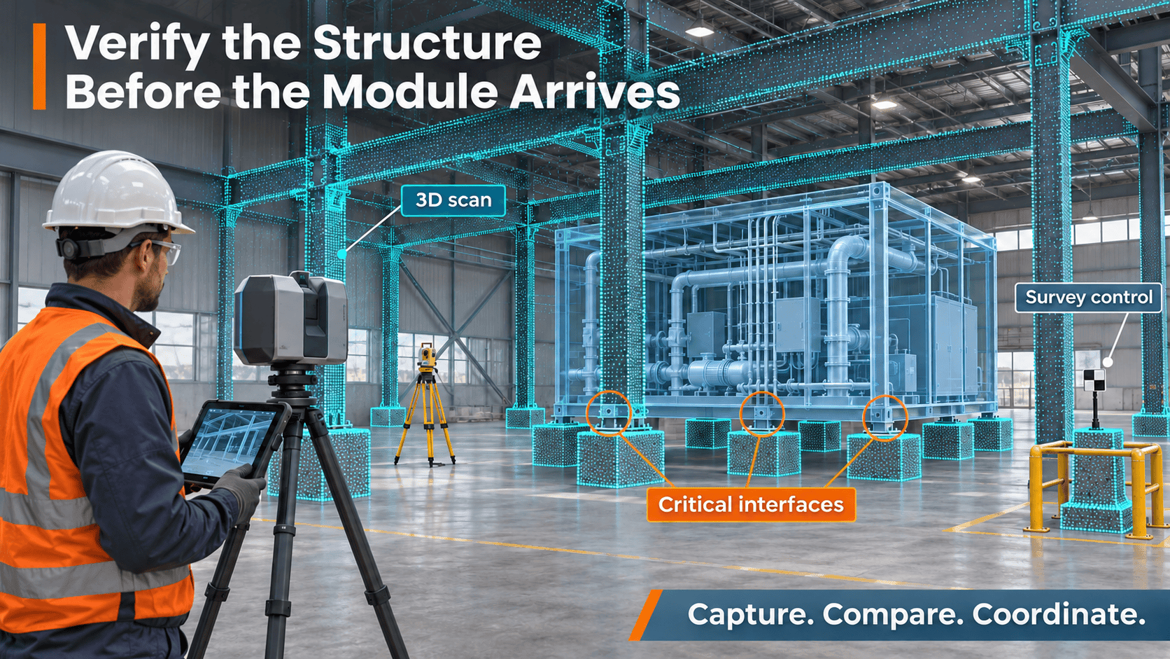
Once the receiving structure is erected, 3D scanning can provide a baseline of its accessible surfaces, openings, and surrounding clearances.
That baseline becomes more useful when it is tied to the project’s survey coordinates and compared with the proposed module geometry.
Before fabrication dimensions or installation interfaces are released, the team should:
- Establish and verify survey control, including stable references appropriate to any movement checks.
- Capture the receiving structure at an agreed construction and loading stage.
- Survey critical support and connection points directly where scanning cannot reliably resolve the required detail.
- Compare the measured interfaces with the module model and its installation clearances.
- Resolve deviations through approved adjustments or design revisions, and define when remeasurement is needed.
A point cloud is a measurement record. The engineering value comes from turning it into checked dimensions, coordinates, and decisions at the interfaces that matter.
The Date of the Scan Is Part of the Data
A scan records a condition at a particular time.
If significant loads are added afterward, or movement remains a concern, that record may need to be updated before installation. Repeat measurements referenced to verified stable control can help identify change. A single scan cannot predict future settlement.
Record the survey date, construction stage, loading condition, coordinate reference, and verification results alongside the geometry.
At MetalMorph, dimensional verification connects field conditions with digital modeling, fabrication, and installation planning.
For modular work, that connection starts before the module arrives: measure the receiving structure, check the critical interfaces, and give the team time to respond.
A well-made module needs a verified place to fit.
MetalMorph | Engineering · Digital Fabrication · Dimensional Verification
References
- [1] FHWA, Geotechnical Engineering Circular No. 6: Shallow Foundations, September 2002. Chapters 5–6 discuss bearing resistance, settlement, and foundation design. Cited for general geotechnical concepts, not as a building-specific code requirement.
- [2] NPTEL, Site Exploration and Geotechnical Investigation, Module 1, Lecture 4, plate load test limitations.
- [3] Hong Kong CEDD, GEO Report No. 72: Long-term Consolidation Tests on Clays from the Chek Lap Kok Formation.
Illustrations are conceptual and are not project records or engineering calculations. Illustrated movement is exaggerated and does not represent a predicted magnitude.

