
One tiny shift. Repeated many times. One very surprised installation crew.
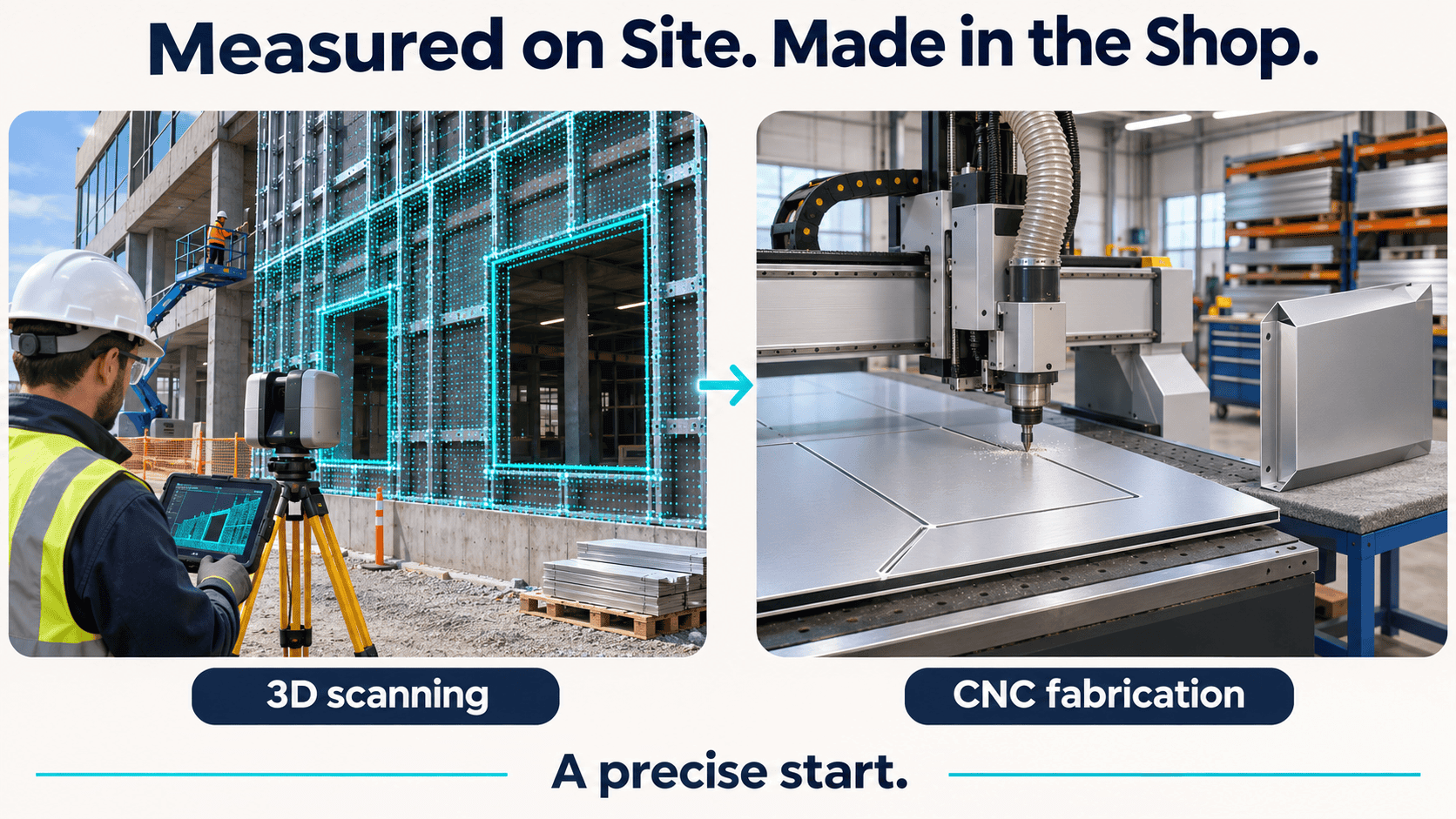
The building was scanned. The dimensions were checked. The aluminum composite material (ACM) panels were cut on a CNC router.
A good start.
But the panels still need to make one more journey—from the workshop to their final positions on the building.
It Fits... So Keep Going?
Imagine the crew installing a long row of panels.
The first one fits. The second one fits. The joints look neat.
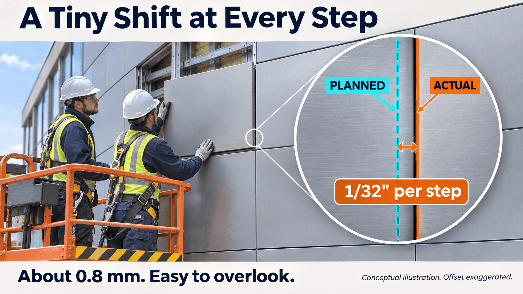
Then one joint ends up just a little wider than planned. Only 1/32 inch—about 0.8 mm.
That is easy to miss by eye, especially while holding a panel on a work platform.
The crew moves on.
The Previous Panel Can Pass the Error Along
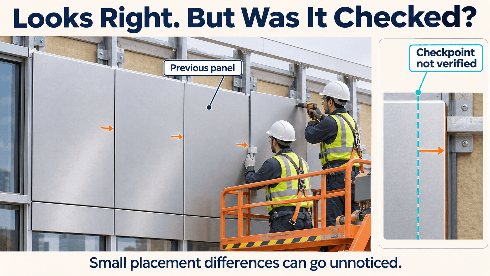
The next panel is positioned from the one already installed.
If that joint is also slightly wider, the new panel moves a little farther along the wall. Repeat the same small difference, and the whole row gradually drifts.
Each panel may look fine beside its neighbor.
But are they still in the right places on the building?
That is why checking against a shared reference line matters. Looking at the previous panel alone may not reveal how far the row has moved.
Now Walk 330 Feet to the Corner
Here is a simple example.
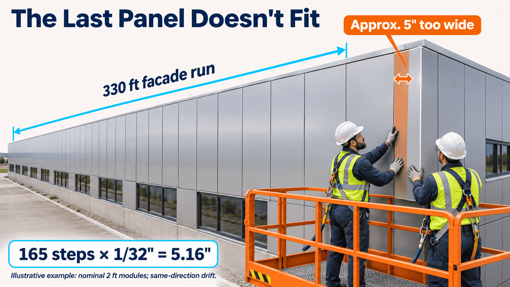
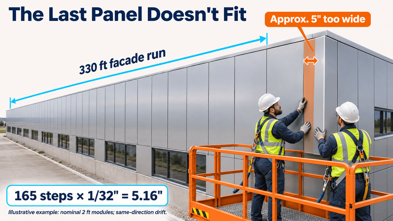
Take a 330-foot facade, with panels and joints repeating roughly every 2 feet. That gives around 165 layout steps.
If each step adds 1/32 inch in the same direction:
165 × 1/32 inch = 5.16 inches.
That tiny difference has become roughly five inches.
Real installation errors can go in different directions. This example shows what happens when the same small shift keeps repeating.
At the corner, the crew lifts the final folded panel into place.
Too wide.
The building corner is exactly where it was. The installed panel row has used up more space than expected.
The last piece has nowhere to go.
“Can We Just Make Another One?”
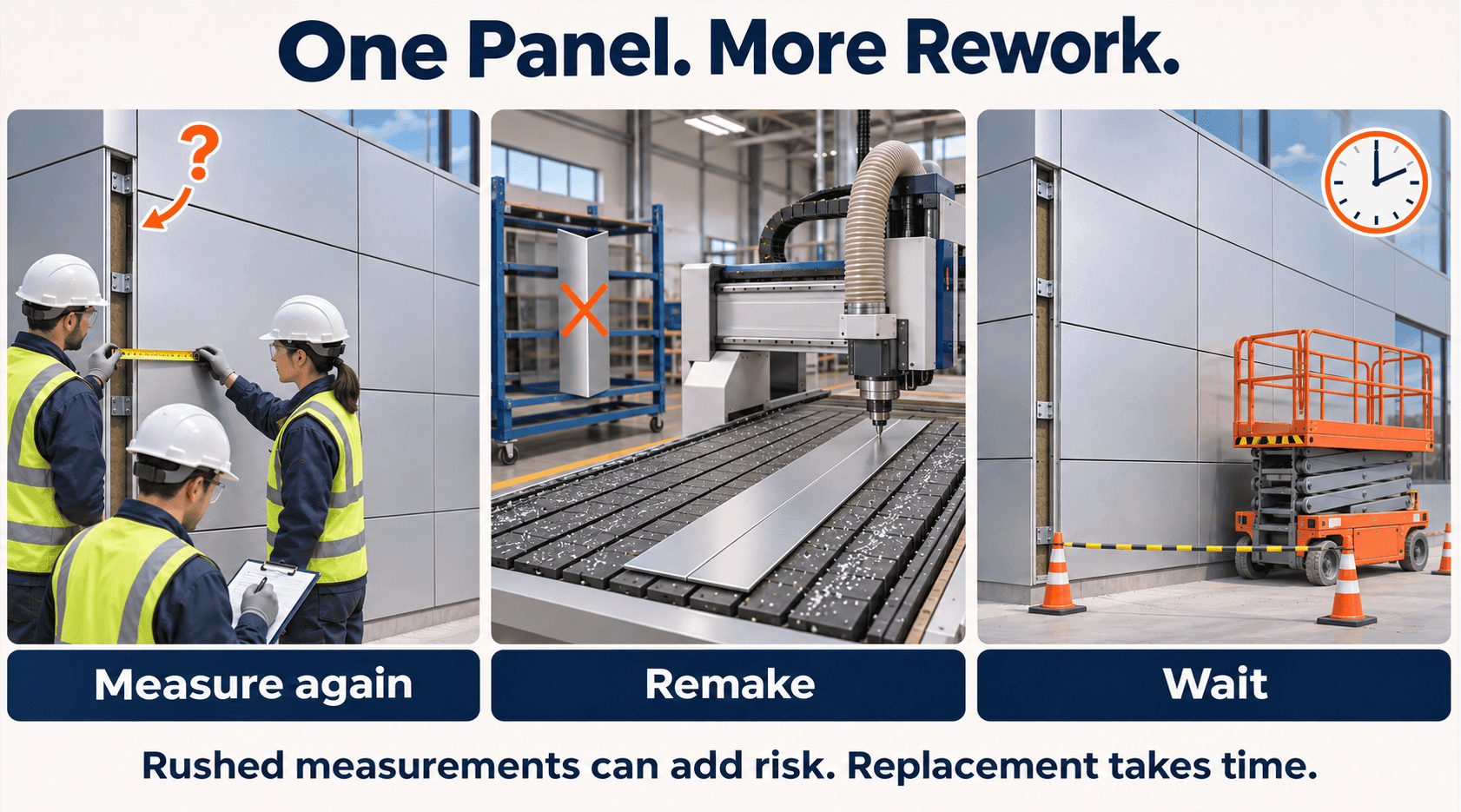
Yes. But first, someone needs to measure it properly.
A corner panel wraps around two faces of the building. Both widths matter. So do the corner angle, fixing positions, and space for the joints.
A tape measure can help. A hurried check of just one dimension may miss something important.
Then comes the extra work: update the drawing, make the replacement, arrange delivery, and return to install it.
Meanwhile, that final corner waits.
Quite a lot of attention for one small piece of metal.
Give the Last Piece a Head Start
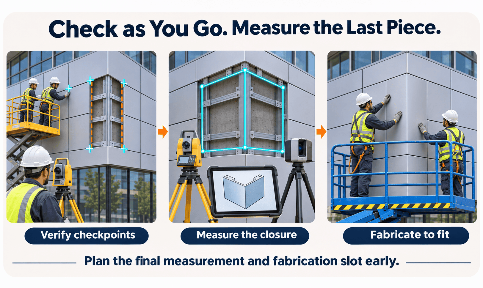
Start with verified site measurements. Then check the panel positions as installation moves along.
Catch small shifts early, while the crew can still correct them.
Where the approved design allows it, leave the final corner panel for a planned field measurement before fabrication. Confirm its actual shape, dimensions, joints, and fixing locations.
Use 3D scanning or targeted survey measurements when the required detail and accuracy call for them. Our earlier article on how accurate a 3D scan needs to be covers how to set that target.
The final piece must still meet the approved design. It cannot fix an installation that has drifted beyond acceptable limits.
And book the measurement, drawing review, fabrication slot, and delivery early. That is how a final measurement can fit into the schedule instead of becoming a last-minute delay.
At MetalMorph, we connect site measurement, fabrication, and installation planning—right through to the last piece.
The last panel should finish the job, not start another round of it.
MetalMorph | Engineering · Digital Fabrication · Dimensional Verification
Conceptual illustrations. Small offsets are exaggerated for visibility.

